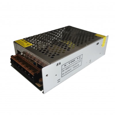
100W SMPS
Industrial control system
Mechanical and electrical equipment
Electronic instrument and equipment
Household appliances
Application:
Industrial automation machinery
Industrial control system
Mechanical and electrical equipment
Electronic instrument and equipment
Household appliances
Features:
Full voltage 90Vac~264 Vac, no switching
Comprehensive protection function: short circuit/overload/overvoltage
Design with full reference to safety regulations and EMC
All electrolytic capacitors with long-life at 105℃
High efficiency, long life and high reliability, 100% full load aging test
Specification
Item | S-100-5 | S-100-12 | S-100-15 | S-100-24 | S-100-36 | S-100-48 | ||
Output | Dc voltage | 5V | 12V | 15V | 24V | 36V | 48V | |
Output light load range | 5V-5.1V | 12V-12.2V | 15V-15.2V | 24-24.2V | 36-36.2V | 48V-48.2V | ||
Output rated current | 18A | 8.3A | 7A | 4.5A | 3 A | 2.3A | ||
Output current range | 0-18A | 0-8.3A | 0-7A | 0-4.5A | 0-3 A | 0-2.3A | ||
Rated output power | 90W | 100W | 105W | 108W | 108W | 110.4W | ||
Ripple&noise (Ta is the ambient temp.) | O < Ta 70℃ | 120mV | 150mV | 150mV | 300mV | 300mV | 500mV | |
Output adjustment range | 4.5-5.5V | 10.5-13.5V | 13.5-16.5V | 21.6-26.4V | 32.4-39.6V | 43.2-52.8V | ||
Voltage stabilization accuracy | ± 2-3% | |||||||
Source adjustment rate @-10-50℃ | ± 0.5% | |||||||
Load adjustment rate | ± 1% | |||||||
Temperature coefficient | ± 0.03%/℃ | |||||||
Output start time | 500ms/(230Vac/115Vac input, Full load) | |||||||
Output hold time | 30mS(230Vac input/115Vac, Full load) | |||||||
Voltage overshoot @-10-50℃ | <5.0% | |||||||
Input | Input voltage range | 90Vac~264Vac 120-370VDC | ||||||
Rated input voltage range | 100Vac~240Vac 120-370VDC | |||||||
Frequency range | 47Hz~63Hz | |||||||
Starting voltage @-30-70 ° C | 90Vac (Refer to the derating curve) | |||||||
Efficiency @25 ° C | 81% | 82% | 83% | 85% | 85.5% | 86% | ||
Input current @25 ° C | <1.9A@115Vac | |||||||
Starting impulse current | <65A@230Vac Cold start | |||||||
Standby power consumption @25℃ | <0.5W | |||||||
Protection |
Output |
Over power | 120%-180% OFF | |||||
Test method: Increase the output current until protection. When protection, it can not cause fire, smoke, electric shock and other dangerous phenomena. It can recover automatically after eliminating overpower. | ||||||||
Over voltage | 5.75-6.9V | 13.8-16.2V | 18.75-21.75V | 28.8-33.6V | 41.4-48.6V | 55.2-64.8V | ||
Test method: Pin 1-3 of short circuit U3; Protection mode: constant voltage. It can not cause fire, smoke, electric shock and other dangerous phenomenon. It can return to normal after eliminating over voltage. Note: Do not use the external voltage to test. | ||||||||
Over current | 120%-180% OFF | |||||||
Test method: The overcurrent point is the current value of the output current increasing until the output voltage falls out of the stable voltage accuracy range. When protection, it can not cause fire, smoke, electric shock and other dangerous phenomena. After eliminating overcurrent, it can automatically resume to normal. | ||||||||
Short circuit | The copper wire with sufficient cross-sectional area and length of 15cm± 5cm is used to short-circuit directly at the output port of the power supply, which can be short-circuit for long time. After eliminating short-circuit, it can be automatically restored | |||||||
Working Enviro-ment | Operating temperature and humidity | 0℃~50℃; 20%~90%RH No condensing | ||||||
Storage temperature and humidity | -20℃~85℃; 10%~95%RH No condensing | |||||||
Vibration | 10 ~ 500Hz, 5G 10min./1cycle, period for60min. each along X,Y, Z axes | |||||||
Impact | 20G/11mS pulse ,3 times at each X,Y,Z axes | |||||||
Altitude | 5000m (Above 2000m, the ambient temperature drops 0.5 ° C for every 100m increase in height) | |||||||
Three prevention requirements | Moisture-proof, mildew proof, salt spray proof | |||||||
Safety standard @25℃ | Safety standard | Refer to UL60950 -1, TUV EN60950 -1, EN60335 -1, EN61558 -1/-2-16 ,CCC GB4943 | ||||||
Insulation strength | Input-output: 1.5KVac/10mA: Input-Housing: 1.5KVac/10mA: Output-Housing: 0.5KVdc/10mA. The test time is 1min | |||||||
Ground test | Test conditions: 40A/2 minutes; Ground impedance: <0.1 ohms. | |||||||
Leakage current | Input to ground 3.5mA; Input to output 0.25mA | |||||||
Insulation negative resistance | Input-output: 100M ohms; Input -- housing: 100M ohms; Output -- Housing: 100M ohms | |||||||
Others | Installation method refers to the instructions. | |||||||
Size | 159*98*42mm | |||||||
Connecting terminal | 95-7 terminal block | |||||||
Reli-ability require-ment
| Design MTBE
| 200,000Hrs AT 25℃, MIL-217 Method 2 Components Stress Method | ||||||
Design electrolytic capacitor life | More than 2 years (test condition: ambient temperature 50℃, input 220Vac, output 100% load) | |||||||
Comments
1. If no other specified, all specifications are tested at 230VAC, rated load, 25℃ ambient temperature.
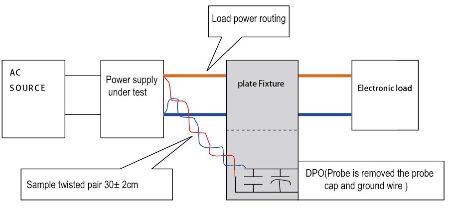
2. The ripple noise is connected by 22# twisted pair wire, the bandwidth of oscilloscope is set to 20MHz, the Teck P3010 100M bandwidth probe is used, and the probe end is connected in parallel with 0.1uF polypropylene capacitor and 10uF electrolytic capacitor. The oscilloscope sampling mode is Sample.
Schematic diagram of output stripe and dynamic test:
Connect the power supply input to AC SOURCE, and the output is connected to the electronic load through the fixture plate. Testing separately with sampling line of 30cm± 2cm from the power output port. Power wires are selected insulated wire with corresponding diameter based on the output current
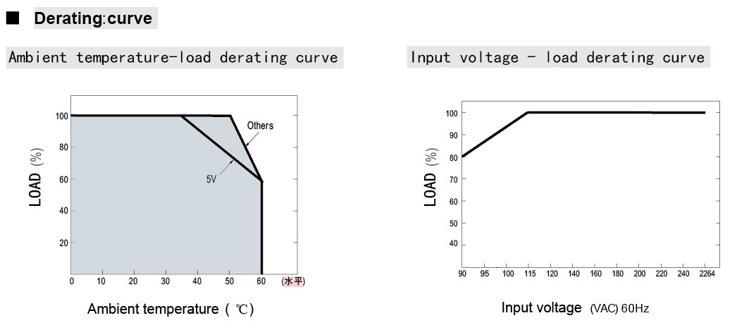
3. Derating must be performed at low voltage or high temperature. For details, see the derating curve.
4. Test conditions: Test voltage is 500VDC;The test is conducted at ambient temperature of 25℃ and relative humidity of 65%RH.
5. The power supply will be installed as a component in the final equipment, which still needs to meet EMC conditions. The criteria are as follows:
A: The performance of the power supply does not allow any degradation compared with the normal condition.
B: The performance of the power supply is allowed to decline, but any kind of reset or function interruption is not allowed.
C: Allow automatic reset of short-term function interruption, and do not allow long-term function interruption or manual reset.
R: The damage of any component other than the protection one is not allowed, and the performance of the specimen can be restored after the replacement of the damaged protection componet.
5. Test conditions: Test voltage is 500VDC; Test conditions: Test at ambient temperature of 25C/65%RH.
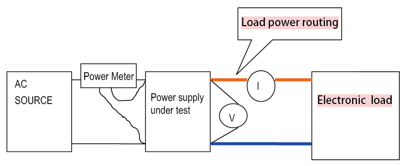
6. Operation method of efficiency test:
Connect the power input to the AC SOURCE and the output to the electronic load. It is recommended to use 22# wires for the sampling line. For the power line, select the insulated wire with the corresponding diameter according to the output current. The input and output voltage measurement points select the ports of power input and output for measurement.
Notes:
The key parameters of the switching power supply are calculated as follows:
1.Source regulation: After the heat engine stabilizes at the rated input voltage and rated load for 15 minutes, measure and record the output voltage V1, VO, and V2 at the lower limit of the input voltage, rated input voltage (Normal), and upper limit of the input voltage.

2.Load regulation: After the heat engine stabilizes at the rated input voltage and rated load of the switching power supply to be tested for 15 minutes, the input voltage is rated input voltage, and the output voltage is recorded as V1, Vo(normal) and V2 when the load is measured at full load, half load and no load respectively.

3.Temperature coefficient: The output voltage Vo (normal) of the switching power supply under rated input voltage and rated load is measured respectively at room temperature, and the output voltage V1 and V2 are measured respectively at the highest temperature and the lowest temperature.

△T1= maximum temperature -- room temperature;
△T2= room temperature - the lowest temperature
4.Voltage set-point accuracy: After the heat engine is stabilized for 15 minutes at the rated input voltage and rated load, a value Vx with the maximum absolute difference between the output voltage and the reference value Vo is measured when the load and input voltage are changed. The reference value VO is measured and recorded as vo when the input voltage is rated input voltage and the load is half loaded.

5.Startup time: under rated input and output conditions, the time from startup to rise to the lower limit of voltage regulator accuracy of output voltage.
6.Holding time: under rated input and output conditions, the time from shutdown to drop to the lower limit of output voltage set-point accuracy. When measuring, the output load is full off and the output end without external capacitance. When measuring shutdown holding time, it should be at 90 degrees phase to cut off the AC input power.
7.The cycle of the output dynamic load characteristic is 4ms, where T1:2mS;T2: 2mS. The current change rate di/dt is 1A/uS.

Installation size:
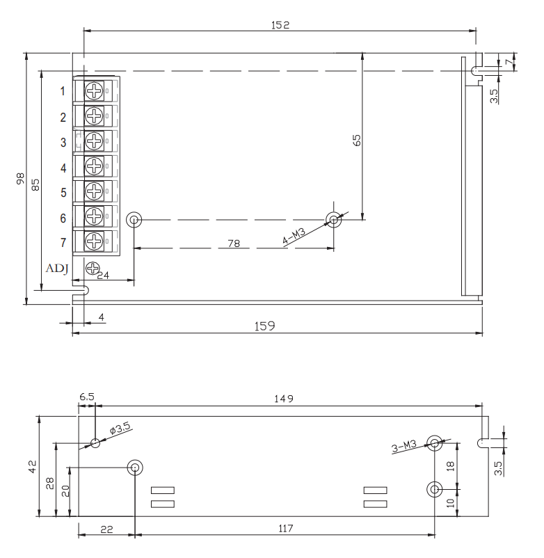
Note:
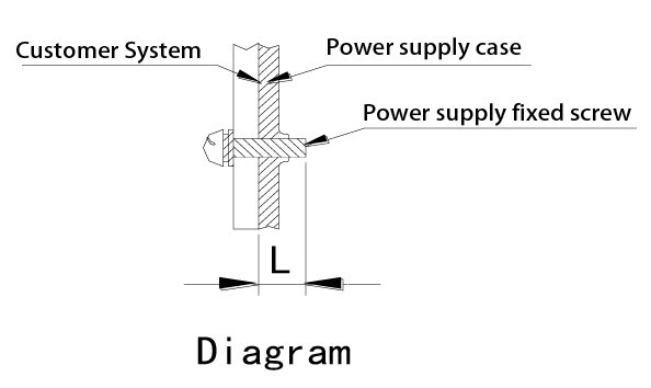
1.Screw into the power supply housing length L (as shown in the right picture).
2. Size unit: mm
3. The tolerance of unmarked dimensions shall be GB/T1804-M Class
4. Select the best module installation mode
AC input installation description:
Position | Fuction | Terminal | Wire Specificaitons | Max torque |
1 | AC-L |
9.5 |
22-12AWG |
12KG/CM(MAX) |
2 | AC-N | |||
3 | GR |
DC output installation description
Position | Fuction | Terminal | Wire Specificaitons | Max torque |
4 | V- | 9.5 | 22-12AWG | 12KG/CM(MAX) |
5 | V+ |
Instructions for installation and use:
1.During installation, please follow the above instructions for installation.
2.Before the installation is complete, please check and proofread the wiring on each terminal, make sure that input and output, AC and DC, positive and negative terminals, voltage and current values are correct, prevent the occurrence of reverse connection error, to avoid damage to the power supply and equipment.
3.Please use a multimeter to measure whether the live wire, neutral wire and ground wire are short-circuited and whether the output terminal is short-circuited before power-on.It is best to start no-load when energized.
4.Do not exceed the nominal value of the power supply, so as not to affect the reliability of the product.If you need to change the output parameters of the power supply, please consult the technical department of our company before using the power supply to ensure the use effect and reliability.
5.In order to ensure the safety of use and reduce interference, please ensure that the grounding terminal is reliably grounded (grounding wire greater than AWG18#.
6.In order to extend the life of the power supply, we can provide air duct design solutions.
7.Do not switch the power supply frequently, otherwise it will affect its life.
8.If the power supply fails, please do not repair it without permission. Please contact the customer service Department of our company as soon as possible.
Packing, transportation and storage:
1.Packaging: The product name, model, manufacturer's logo, manufacturer's quality department inspection certificate, manufacturing date, etc., shall be marked on the packing box.
2.Transportation: The packaging is suitable for transportation by car, ship, plane, train, etc. During transportation, it should be rainproof and loaded and unloaded in a civilized manner.
3.Storage: the product is not used should be placed in the packing box, storage environment temperature and relative humidity should meet the requirements of the product, there should be no corrosive gas or products in the warehouse, and no strong mechanical vibration, impact and strong magnetic field.The packing case should be padded at least 20cm above the ground and protected from water.If the storage time is too long (more than 1 year), it should be re-inspected by professional personnel before use.


