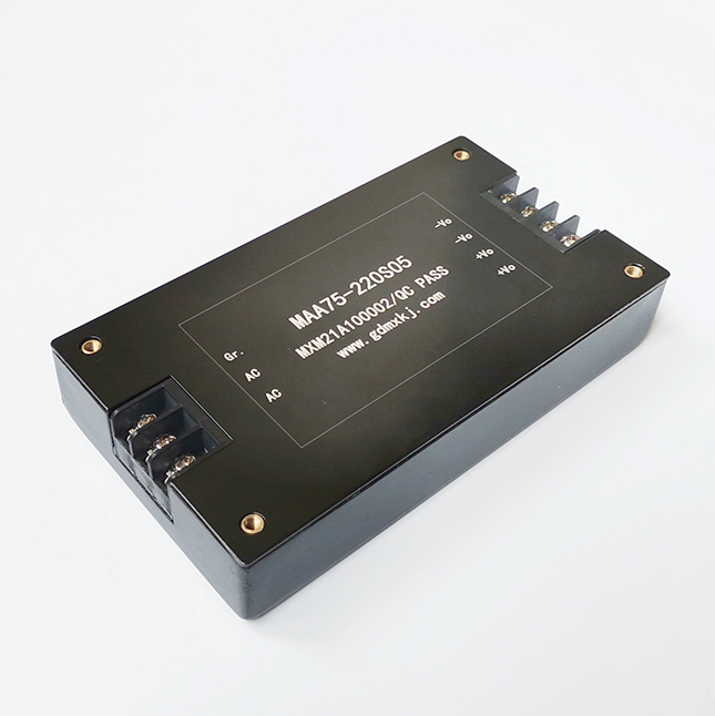
What does a DC conversion power supply look like?(2)

DC conversion Marine boost voltage power supply The distinction between good circuit principles and bad circuit principles can often only be made from a professional perspective. At this stage, power modules can be roughly divided into two types: bare board and potting. The bare board can be based on intuitive methods, such as the layout of electronic components is reasonable, neat, generous, neat, and the solder joints are bright and straight. For encapsulated modules, it is not possible to see the internal conditions, but since the internal conditions are not exposed, it is much better in terms of safety and performance metrics. The soldering process can include hand soldering and wave soldering. The quality of the wave soldering process of mechanized production is better than that of manual soldering.
Drive module power supply
The frequency converter power supply is mainly used for the frequency conversion and speed regulation of the AC motor. The main circuit of the inverter power supply adopts the AC-DC-AC scheme. The power frequency power supply becomes a fixed DC voltage through a rectifier, and then a PWM high-frequency converter composed of high-power transistors or IGBTs inverts the DC voltage into an AC output with variable voltage and frequency. The output waveform of the power supply is similar to a sine wave. It is used to drive the AC asynchronous motor to realize stepless speed regulation.
DC conversion Marine boost voltage power supply Two: chip components
The core of the Marine boost voltage power supply is the IC, just like the brain of the Marine boost voltage power supply, the quality of the IC directly affects various parameters of the Marine boost voltage power supply.

